
Workmanship is a critical component of any electrical installation, particularly in high power and high current applications. While design and specification are often given significant attention, the quality of installation can materially influence both system performance and safety outcomes.
This article examines the behaviour of resin-encased bus duct systems under fault conditions and explores how installation quality can directly impact arc flash risk. A real-world case study is presented to illustrate the consequences of inadequate workmanship and to outline practical mitigation strategies.
Bus Ducts in High Current Applications
Bus ducts are commonly used for the distribution of large currents in low voltage systems, particularly between transformers and main switchboards. While widely applied, they are not always as well understood as conventional cable systems.
A bus duct system typically consists of rigid conductors enclosed within a protective housing. In the case of resin-encased designs, the insulation and structural integrity are provided by a solid resin material surrounding the conductors.
The advantages of bus ducts become apparent in high current scenarios. For example, a 2.5 MVA transformer operating at low voltage produces a full load current of approximately 3600 A. Using conventional 500 mm² copper cables (with an approximate capacity of 800 A), this would require five to six parallel cables per phase. Such an arrangement presents significant challenges in installation, termination, and space constraints. Wrangling and terminating such cables would be quite an arduous task. In some cases, it would prove virtually impossible to achieve this type of installation with cable. This is one of the big benefits of bus duct and why bus ducts offer a more compact and constructible alternative.
Bus duct systems are typically categorised as either metallic encased (air insulated) or resin encased (solid insulated).
Within the Metallic Encased version it is common to see a tubular casing resembling a steel pipe with flanges or alternatively it may have a rectangular sheet metal type casing. Phases can either be isolated (in their own enclosures) or segregated (with partitions) or have no segregation and just rely on air gap for insulation.
Resin-encased systems are often preferred due to their compact form factor and integrated insulation, with conductor spacing typically in the order of 7–8 mm. The remainder of this article considers resin-encased systems only.
Installation Considerations
Resin-encased bus ducts are generally supplied in prefabricated sections, with site-installed joints formed by pouring resin around exposed conductor connections. These joints are critical to the overall integrity of the system.
The image below shows some example sections. Ends are left exposed to allow jointing with a subsequent section (refer mark C) and then a mould is placed around the joint with a resin then poured around the joint area in situ. The jointed area is typically wider as shown by mark B. Mark A shows the final termination palms which would terminate to a switchboard or transformer. Mark D shows typical vertical mounted supports.
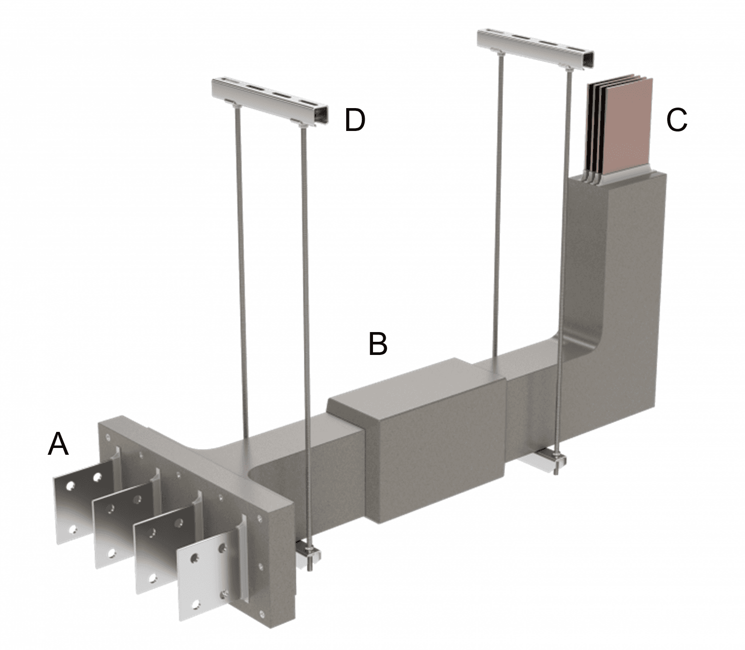
The quality of these site-made joints is highly dependent on installation practices, including correct resin mixing, pouring techniques, and environmental control during curing. Deficiencies in any of these aspects can introduce voids or air inclusions within the insulation system.
As will be demonstrated, these seemingly minor imperfections can have significant consequences under fault conditions.
Case Study Overview
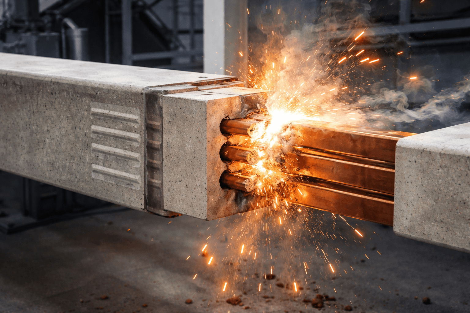
A facility was observed to experience repeated failures of resin-encased bus duct systems, with five failures occurring over a five-year period. These failures were not minor in nature; several involved significant arc flash events, evidenced by molten copper ejection and associated thermal damage to surrounding infrastructure (as documented in the case study material).
The failures occurred under normal operating conditions and were not associated with switching events, indicating an underlying systemic issue.
Root Cause Analysis
A structured investigation was undertaken to identify the root cause of the failures. Potential contributing factors considered included:
Structural movement of the building
Environmental conditions
Mechanical damage
Installation quality
The distribution of failures across both indoor and outdoor installations, including environmentally controlled switchrooms, allowed environmental and structural causes to be largely excluded. Similarly, the inaccessibility of many installations reduced the likelihood of mechanical damage.
The investigation ultimately identified workmanship as the primary contributing factor. Non-destructive testing and physical inspection revealed the presence of voids and air bubbles within the resin at joint locations. These defects are consistent with improper mixing or pouring of resin during installation and create localised weakness in dielectric strength.
This finding reinforces a key principle that the performance of a system is not solely determined by design, but also by execution.
Arc Flash Risk Assessment
The presence of insulation in resin-encased bus ducts may lead to the assumption that arc flash risk is negligible. However, the observed failures demonstrate that under certain conditions, this assumption is not valid.
Arc flash risk was assessed using the IEEE 1584 methodology, with the bus duct modelled conservatively as an “in-air” system due to the absence of established models for arc propagation within resin. A conductor gap of 7 mm was adopted to reflect the physical configuration.
The results indicated incident energy levels ranging up to approximately 16 cal/cm², with arc flash boundaries extending several metres. These values are consistent with the physical damage observed during failure events and represent a credible hazard to personnel.
Safety Risk Reduction
A number of mitigation strategies were evaluated, including thermal monitoring and physical shielding. However, these approaches were ultimately deemed insufficient due to limitations in response time, effectiveness, and practicality in live installations.
The selected solution was the implementation of differential protection across the bus duct length. By measuring current at both ends of the duct and detecting imbalances, faults can be identified and cleared rapidly without the need for coordination delays.
Implementation involved upgrading protection relays and installing additional current transformers. Following this upgrade, recalculated incident energy levels were reduced to below 0.5 cal/cm², representing a substantial improvement in safety performance.
Production Risk Considerations
While differential protection is effective in limiting arc flash energy, it does not eliminate equipment damage or loss of supply. For facilities with high production dependency, this remains a critical consideration.
Repair of resin-encased bus ducts presents several challenges. The removal of damaged sections requires specialised procedures due to silica dust, and partial repairs do not address latent defects in remaining joints. Furthermore, mechanical disturbance during repair may introduce additional defects.
Complete replacement of the bus duct system was therefore considered the only method of fully mitigating both safety and reliability risks.
Alternative Solutions
The installation of a new bus duct system in an operational environment is often impractical. Similarly, reverting to conventional cabling may not be feasible due to space and constructability constraints.
A hybrid solution utilising a flexible bus system (nVent fleXbus, no paid promotion) was ultimately adopted. This approach provided the higher current-carrying capacity of a bus duct while allowing installation alongside existing infrastructure. A staged cutover strategy enabled the system to remain energised until final commissioning.
This solution also allowed the existing bus ducts to remain in place, avoiding the risks associated with removal and providing a contingency supply path if required.
Conclusion
Resin-encased bus duct systems remain an effective solution for high current distribution. However, this case study demonstrates that their performance is highly dependent on installation quality, particularly at joint locations.
The assumption that such systems do not present an arc flash risk is not universally valid. Where workmanship is uncertain, it is prudent to assess the potential incident energy and incorporate bus ducts into arc flash studies.
Mitigation strategies should prioritise engineering controls, such as differential protection, and consider system replacement where reliability is critical.
Ultimately, ensuring both safety and performance requires a holistic approach that considers not only design, but also installation quality and lifecycle risk.